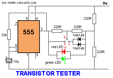
TRANSISTOR TESTER Circuit

The 555 operates at
2Hz. Output pin 3 drives the circuit with a positive then zero
voltage. The other end of the circuit is connected to a voltage
divider with the mid-point at approx 4.5v. This allows the red and
green LEDs to alternately flash when no transistor
is connected to the tester.
If a good transistor is connected, it will produce a short across
the LED pair when the voltage is in one direction and only one LED
will flash. If the transistor
is open, both LED's will flash and if the transistor is
shorted, neither LED will flash.
View All Circuits


