THE SIMPLEST 555 OSCILLATOR Circuit
The simplest 555 oscillator takes output pin 3 to capacitor C1 via resistor R1.
When the circuit is turned on, C1 is uncharged and output pin 3 is
HIGH. C1 charges via R1 and when Pin 6 detects 2/3 rail voltage, output
pin 3 goes LOW. R1 now discharges capacitor C1 and when pin 2
detects 1/3 rail voltage, output pin 3 goes HIGH to repeat the
cycle:
 CHANGING THE MARK-SPACE RATIO
The amount of time when the
output is HIGH is called the MARK and the time when the output is
LOW is called the SPACE.
In the above diagram the mark is the same length as the space and
this is called 1:1
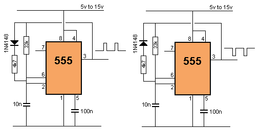
This ratio can be altered by adding a diode and resistor as shown in
the following diagrams. In the first diagram, the 555 comes ON with
pin 3 low and pin 3 immediately detects this low and makes pin 3
HIGH. The 10n is quickly charged via the diode and 4k7 and this is
why the MARK is "short." When the capacitor is 2/3Vcc, pin 6 detects
a HIGH and the output of the 555 goes LOW. The 10n is discharged via
the 33k and this creates the long-duration SPACE (LOW). The second
diagram creates a long-duration HIGH:
 View All Circuits


