555 Timers are fun and a great way to start learning electronics
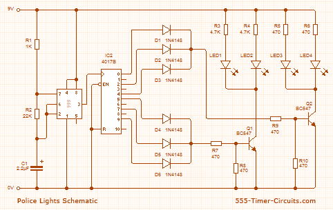
POLICE LIGHTS Circuit
This circuit flashes the left LEDs 3 times then the right LEDs 3 times, then repeats.
Overview
This circuit uses a 555 timer which is setup to both runn in an Astable operating mode. This generates a continuous output via Pin 3 in the form of a square wave. When the timer's output changes to a high state this triggers the a cycle on the 4017 4017 decade counter telling it to output the next sequential output high. The outputs of the 4017 are connected to the LEDs turning them on and off.
Schematic
Video
This video walks you through building this circuit using a breadboard.