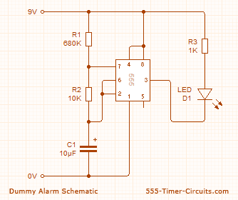
DUMMY ALARM Circuit
This Dummy Alarm project makes an LED flash briefly once every 5 seconds to imitate the indicator light of a real alarm.
Overview
The circuit is designed to use very little current to prolong battery life so that it can be left on permanently. An on/off switch is not included, but could be added if you wish. The 7555 timer IC used is a low power version of the standard 555 timer. A 'superbright' red LED is used because this provides a bright flash with a low current. The LED is off for most of the time so the average total current for the circuit is less than 0.2mA. With this very low current a set of 3 alkaline AA cells should last for several months, maybe as long as a year.
Schematic
 Parts List
1x - NE555 Bipolar Timer
1x - LED (Red)
1x - 680K Resistor (1/4W)
1x - 1K Resistor (1/4W)
1x - 10K Resistor (1/4W)
1x - 10µF Electrolytic Capacitor (16V)
1x - 9V Voltage Battery
View All Circuits


